Search

phpmyadmin ssh tunnel

I have multiple webservers running a debian jessie LAMP installation. I do not want to install phpmyadmin on all of them so a central installation is necessary. I chose to set up a ssh tunnel to each server that is opened at boot and uses autossh for persistance. phpmyadmin is then configured with the additional servers to enable simple connectivity.

To /etc/rc.local I’ve added a line for each server (with an increasing local port, here 3307) for the persistent tunnel.

/usr/bin/autossh -M 0 -q -f -N -o "ServerAliveInterval 60" -o "ServerAliveCountMax 3" -L 3307:localhost:3306 root@domain.tld.

I also added a corresponding section to /etc/phpmyadmin/config.inc.php at the end of the server section.

$cfg['Servers'][$i]['verbose']       = 'domain.tld';
$cfg['Servers'][$i]['host']          = '127.0.0.1';
$cfg['Servers'][$i]['port']          = '3307';
$cfg['Servers'][$i]['connect_type']  = 'tcp';
$cfg['Servers'][$i]['extension']     = 'mysqli';
$cfg['Servers'][$i]['compress']      = FALSE;
$cfg['Servers'][$i]['auth_type']     = 'cookie';
$i++;

In this way I have set up a centralized phpmyadmin without opening up any additional ports on any server.

FrSky telemetry with arduino

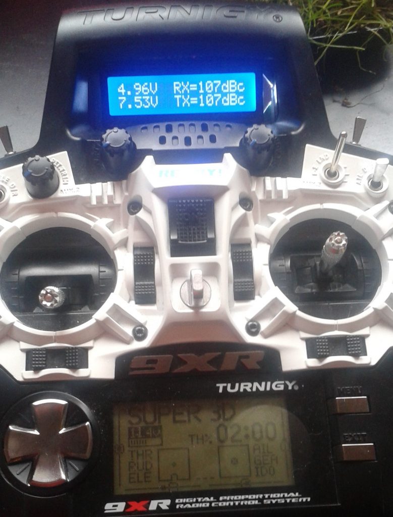
I decided it would be useful having telemetry on my 9xr, but I disliked the existing hardware mods and decided to try to use the port on the back of the djt module and connect a hd44780 display and an arduino nano. The tricky part was inverting the signal by using SoftwareSerial instead of hardware.

I’m very pleased with the result. Showing A1, A2, RSSI for both rx and tx. On the receiver side I’m using a voltage divider with 10k and 2k2 resistors hooked up to A2.
9XR Telemetry

#include <SoftwareSerial.h>
#include <LiquidCrystal.h>
 
#define DE_BUG                          // Change this to #define DEBUG if needed
#define DE_BUG_HEX
#define FRS_TX_PIN        A2            // not used
#define FRS_RX_PIN        A3            // telemetry data
#define FRAME_SIZE        12            // max 12 bytes
#define FRAME_RVLQ      0xFE            // second byte 0xFE - Remote Voltage and Link Quality
#define FRAME_USER      0xFD            // second byte 0xFD - User Data
#define DISP_INTERVAL    500            // ms
 
SoftwareSerial FrSky = SoftwareSerial(FRS_TX_PIN, FRS_RX_PIN, true);  // orig false
LiquidCrystal lcd(2, 3, 4, 5, 6, 7 );
 
byte next = 0;
byte buff[FRAME_SIZE];                  // frame array
byte index  = 0;                        // index in frame array
byte link   = 0;                        // link established, data received
byte frame  = 0;                        // frame received indicator
byte stuff  = 0;                        // byte stuffing indicator
int Rx[DISP_INTERVAL/15];               // Up Link Quality RSSI
int Tx[DISP_INTERVAL/15];               // Down Link Quality RSSI
int V1[DISP_INTERVAL/15];               // Port 1 voltage, V * 100
int V2[DISP_INTERVAL/15];               // Port 2 voltage, V * 100
unsigned long dispTime = 0;             // time when info was updated, ms
unsigned long prevTime = 0;             // time when 0xFE frame was received, ms
int frmeTime = 0;                       // frame period, ms (~36ms)
int nvals = 0;                          // number of values received since last display
 
void setup() {
  FrSky.begin(9600);
  Serial.begin(115200);
  dispTime = millis();
  lcd.begin(16, 2);
  lcd.setCursor(0, 0);
  lcd.print("FrSky Telemetry");
  lcd.setCursor(0, 1);
  lcd.print("Filip Grano 2015");
 
  frame = 0;
  index = 0;
  link  = 0;
  stuff = 0;
  prevTime = millis();
}
 
void loop() {
  if (FrSky.available()) {              // reading input data
    next = (byte)FrSky.read();
    if (next != 0x7E)
      if (next == 0x7D)                 // byte stuffing indicator
        stuff = 1;                      // set the flag and discard byte
      else if (stuff == 0)
        buff[index++] = next;         // normal byte
      else {
        buff[index++] = next | 0x20;  // byte stuffing set, change next byte
        stuff = 0;                    // and reset the flag
      }
    else {
      if (index == 10 || index == 11) { // end byte
        buff[index] = next;
        frame = 1;
        index = 0;
      } else {                          // start byte?
        index = 0;
        buff[index++] = next;
      }
    }
    if (index >= FRAME_SIZE)
      index = FRAME_SIZE - 1;           // prevent buffer overflow
  }
 
  if (buff[1] == FRAME_RVLQ && frame == 1) {  // second byte 0xFE - Remote Voltage and Link Quality
    V1[nvals] =  buff[2] * 4 * 330.0 / 255;          // V1 - Voltage, up to 13.2V, Internal divider 1:4
    V2[nvals] =  buff[3] * (22 + 100) / 22 * 330.0 / 255;          // V2 - Voltage, up to 18.3V
    Rx[nvals] =  buff[4];                            // Up Link Quality RSSI   (min 36, max 116-121)
    Tx[nvals] =  buff[5] / 2;                        // Down Link Quality RSSI (min 36, max 116-121)
    frmeTime = millis() - prevTime;           // frame period in ms
    prevTime = millis();
    frame = 0;
    link = 1;    // valid data received
 
    nvals++;
  }
 
  if (link == 1 && millis() > dispTime + DISP_INTERVAL && nvals > 0) {
    dispTime = millis();
#ifdef DEBUG
    printData();
#endif
 
    lcd.setCursor(0, 0);
    lcd.print(mode(V1, nvals) / 100.0, 2);
    lcd.print("V  "); 
    lcd.setCursor(7, 0);
    lcd.print("RX="); 
    lcd.print(mode(Rx, nvals), 1);
    lcd.print("dBc ");
    lcd.setCursor(0, 1);
    lcd.print(mode(V2, nvals) / 100.0, 2);
    lcd.print("V  "); 
    lcd.setCursor(7, 1);
    lcd.print("TX="); 
    lcd.print(mode(Tx, nvals), 1);
    lcd.print("dBc ");
 
    nvals=0;
  }
}
 
void printData(void) {
  Serial.print(prevTime / 1000.0, 4);
  Serial.print(": ");
 
#ifdef DEBUG_HEX
  for (byte i = 0; i <= 10; i++) {
    Serial.print(buff[i], HEX);
    Serial.print(" ");
  }
#endif
 
  Serial.print("V1 = ");
  Serial.print(mode(V1, nvals) / 100.0, 2);
  Serial.print("V, V2 = ");
  Serial.print(mode(V2, nvals) / 100.0, 2);
  Serial.print("V, Rx = ");
  Serial.print(mode(Rx, nvals));
  Serial.print("dBc, Tx = ");
  Serial.print(mode(Tx, nvals));
  Serial.print("dBc, packets = ");
  Serial.print(nvals);
  Serial.println();
}
 
int mode(int arr[], int asize) {
  if (asize==0) { return 0; }
  int mode = arr[asize-1];
  int mcount = 1;
  int count = 0;
 
  for(int i=asize; i>0; i--) {
    int val = arr[i-1];
 
    for(int j=i; j>0; j--) {
      if(arr[j-1] == val) count++;
    }
 
    if (count > mcount) {
      mode = val;
      mcount = count;  
    }
 
    count = 0;
  }
 
  return mode;
}

Used this forum post as a place to start.

Connecting Turnigy 9XR with Arduino ISP

Installing my usbASP drivers failed miserably on my PC, so I decided to use my Arduino Uno to flash OpenTX on my Turnigy 9XR radio controller.

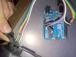
Connecting the controller was very simple once I figured out the orientation of the ISP header on the controller. Use your multimeter to find the GND pin of the header and then connect according to the pin order in the ArduinoISP sketch (there’s a power connector beside the ISP header). You also need to disable reset on the UNO by adding a cap between reset and gnd.
2015-03-09 09.36.26

The trick to getting it to work in OpenTX Companion is the correct avrdude configuration, especially the “-b 19200” extra argument that I found out with trial and error playing with the switches in a terminal.
avrdude_conf

Before I added the extra argument I was getting the typical sync errors 0x00 and 0xe0.

Seems to work OK now! 🙂

—-
Edit:
EEPROM reading and writing was failing, i needed to change the ArduinoISP sketch as described in: http://theboredengineers.com/2013/01/flashing-a-turnigy-9x-with-an-arduino/.
Was failing with verification and corrupt EEPROM errors previously.

Nexa remote socket teardown

I have been fiddling with remote sockets for a couple of years now, especially Nexa branded ones. Yesterday, for the first time, I believe the relay has broken in one of the oldest ones -> Teardown time!

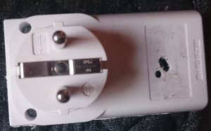
There are some kind of screws that I have never seen before holding the thing together. I tried to heat a pen to make a plastic “quick fix” screwdriver, but the screws were too tight and the “quick fix” screwdriver was not capable of delivering the required torque.
Nexa_back01

I used a utility knife, heated glowing hot with a blowtorch, to cut the enclosure. The result wasn’t pretty but it got the job done.
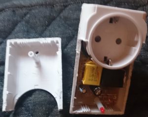
Nexa_front_opened01

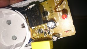
Inside immediately visible relay and three caps: a yellow .22uF 275V, 100uF 50V electrolytic, 10uF 50v electrolytic. Down to the right looks like antenna.

2014-12-20 01.01.14

Under the plastic cap there is what looks very much like a bridge rectifier and a transformerless power supply. There are 2 zeners (ZD201 & ZD202), interesting…

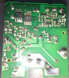
The other side of the board has to house the logic and 433.92 MHz RX.

nexa_board_back_01

One of the chips seems to have no visible text, while the other one is clearly a serial EEPROM HT24LC02.

This does look quite interesting, will have to do some more poking another day 🙂

Update:
The relay is 24V, this has also been suggested as a good option for powering a relay an uC from a transformerless power supply that cannot provide much current (DESIGNER
CIRCUITS, LLC – DesignNote 001a)

Linux default gateway failover

I have an “unreliable” (I sometimes just take it with me) mifi box with fast LTE connection, shared to internal network via separate gateway, and a reliable but slow ADSL connection. I use the following script to switch to the slower connection when the default one is not working and automatically switch back when possible. It’s run by cron every minute on multiple devices.

#!/bin/bash
 
#*********************************************************************
#       Configuration
#*********************************************************************
DEF_GATEWAY="192.168.1.21"      # Default Gateway
BCK_GATEWAY="192.168.1.1"       # Backup Gateway
RMT_IP_1="193.166.3.2"          # first remote ip
RMT_IP_2="8.8.8.8"              # second remote ip
PING_TIMEOUT="1"                # Ping timeout in seconds
#*********************************************************************
 
# check user
if [ `whoami` != "root" ]
then
        echo "Failover script must be run as root!"
        exit 1
fi
 
#Check GW
CURRENT_GW=`ip route show | grep default | awk '{ print $3 }'`
if [ "$CURRENT_GW" == "$DEF_GATEWAY" ]
then
        ping -c 2 -W $PING_TIMEOUT $RMT_IP_1 > /dev/null
        PING_1=$?
        ping -c 2 -W $PING_TIMEOUT $RMT_IP_2 > /dev/null
        PING_2=$?
else
        # add static routes to remote ip's
        ip route add $RMT_IP_1 via $DEF_GATEWAY
        ip route add $RMT_IP_2 via $DEF_GATEWAY
        ping -c 2 -W $PING_TIMEOUT $RMT_IP_1 > /dev/null
        PING_1=$?
        ping -c 2 -W $PING_TIMEOUT $RMT_IP_2 > /dev/null
        PING_2=$?
        # del static route to remote ip's
        ip route del $RMT_IP_1
        ip route del $RMT_IP_2
fi
 
LOG_TIME=`date +%b' '%d' '%T`
 
if [ "$PING_1" == "1" ] && [ "$PING_2" == "1" ]
then
        if [ "$CURRENT_GW" == "$DEF_GATEWAY" ]
        then
                ip route del default
                ip route add default via $BCK_GATEWAY
                # flushing routing cache
                ip route flush cache
                echo "$LOG_TIME: $0 - switched Gateway to Backup with IP $BCK_GATEWAY"
        fi
 
elif [ "$CURRENT_GW" != "$DEF_GATEWAY" ]
then
        # switching to default
        ip route del default
        ip route add default via $DEF_GATEWAY
        ip route flush cache
        echo "$LOG_TIME: $0 - Gateway switched to Default with IP $DEF_GATEWAY"
fi

Disable What’s New App on xperia devices without root

Got my beautiful XPERIA Z3 compact a couple of days ago and was instantly very annoyed at the completely useless What’s New -app, since it was integrated even in the launcher of all places.. Here’s how to remove it without root, idea from talk.sonymobile.com: Get-rid-of-What-s-New

root@Basecamp-Debian:/home/filip# adb shell
shell@D5803:/ $ pm block com.sonymobile.advancedwidget.entrance                
Package com.sonymobile.advancedwidget.entrance new blocked state: true
shell@D5803:/ $ exit

To unblock the app run

pm unblock com.sonymobile.advancedwidget.entrance

Edit: on lollipop replace block with hide!

Move changed files to a separate directory (Linux)

I have previously used hardlinking and rsync to backup my systems. I now have a lot of hardlinked directories with almost the same content in folder structures such as etc.0, etc.1 etcetera (etc.0 being the newest) up to 60.

Cleanup script follows:

#!/bin/bash
 
for i in {1..60}
do
        rsync -a --verbose --compare-dest=../etc.$((i-1)) etc.$i/ etc.diff.$i
        find etc.diff.$i -depth -type d -empty -delete
done

USB fuse bypass for RPi B rev. 0003

My raspberry pi didn’t supply enough current to the connected usb devices and I didn’t want a usb hub so something had to be done..

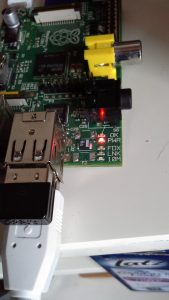
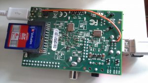
Got the idea from Larry_Adlards post (Sun Jun 17, 2012) to raspberrypi.org/forums/viewtopic.php?f=63&t=8591 but since my rev 3 board did not have polyfuses F1 and F2 (they were shorted) I had to also remove those shorts.

The 5v line on the pi usb port is now 5.04v while before the mod it was ~4,3V with the devices attached (below spec).

Two network adapters, how to change the preferred (Windows)?

It’s decided by the Gateway metric. In my case I want to make the first one the preferred one, so I have to change the “InterfaceMetric: 20” to a value smaller than 10.

C:UsersFilip>route print
IPv4 Route Table
===========================================================================
Active Routes:
Network Destination        Netmask          Gateway       Interface  Metric
          0.0.0.0          0.0.0.0      192.168.1.1    192.168.1.107     10
          0.0.0.0          0.0.0.0         10.1.1.1         10.1.1.2     20

Open Interface Properties -> Internet Protocol Version 4 Properties -> Advanced -> Uncheck Automatic metric and enter 9 -> OK. Done.

10 bit PWM on ATmega32u4 (ex. Arduino Micro)

Some magic is required to get 10 bit PWM on ATmega32u4.

Setup:

  pinMode(13, OUTPUT);
  pinMode(10, OUTPUT);
 
  // 10-bit operation
  TC4H = 0x03; OCR4C = 0xFF;
  //Configuration of Timer 4 Registers, OC4A (D13) + 0C4B (D10)
  TCCR4A = 0b10100011;
  //Prescaler
  TCCR4B = 0b00000011;

Set PWM output value, needs to be written separately to upper and lower register, in this order!

void setPwmDutyA(int val){
  TC4H = val >> 8;
  OCR4A = 0xFF & val;
}
 
void setPwmDutyB(int val){
  TC4H = val >> 8;
  OCR4B = 0xFF & val;
}